| |
LAYOUT DRAWING: TUTORIAL
Step 9: CLOSING THE LAYOUT LOOP -
"COPY" OPERATION - CHECK AND BUILD MODULE
We now want to close the layout oval.
Since the length of the turnout selected from catalog in 20cm, and is thus equal to the length of the second straight
track (up right), the simplest way to close the loop
is as follows:
-
copy the first placed segment (about 100 cm), and snap the copy to the turnout,
-
then add 4 arc segments identical to those used on the right side of the layout.
This is the goal of this step.
COPY THE STRAIGHT SEGMENT
Icon "Copy segment" is the fourth blue icon, starting from left (figure 9-1).

Figure 9-1: "Copy segment" icon.
The sequence for coying out a segment is very similar to the move sequence, already used in step 5:
-
Click on "Copy segment" icon (figure 9-1),
-
Click on segment to be copied out (figure 9-2): the segment is highlighted in white,
-
Click on the "reference port" (the one which will be snapped to another segment).
In the present case, this the right end of the segment.
The segment skeleton then follows the mouse.
-
Bring the mouse close to the left end of the turnout (figure 9-3) until snapping occurs.
-
Click for final positionning.
Note than the "copy" operation (like all other operations, move, delete, ...) can be applied to a group of
several segments, thanks to the multiple selection feature, as will be explained later on in this tutorial.
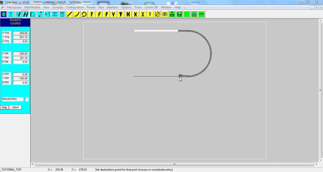
Figure 9-2: copying out the straight segment.
DRAW THE LEFT SEMI-CIRCLE
In order to draw the semi-circle on the left of the layout, we could readily use the "Circular link" primitive
(which will be introduced in next step), to draw in on single shot the whole semi-circle, with automatic snapping
on both free ends of the straight segments.
But in this step, we are going to use 4 arc segments, identical to those used on the right-hand semi-circle.
We could obviously reuse the "add arc" approach used in step 6, and renter the radius and angle values, as done
in step 6.
We also could use the "Copy" operation as for the straight segment.
But here, we are going to do it another way: we are going to retrieve the parameters of already placed curves,
so that they will be automatically reused when clicking the "Add arc segment" icon.
The sequence of operations is as follows:
-
Click on icon "Segment info" (second leftmost blue icon).

Figure 9-3: "Segment info" icon
-
Select one of the "arc" segment (curves) already placed on the right of the layout: the parameter and
coordinate menus appear on left of screen.
This selection operation is sufficient in order to memorize the curve parameters.
-
Click on icon "Add arc segment" (second yellow icon): the parameter and coordinate menus appear, with
correct parameter values. The only thing to modifiy, if we want to start from the top segment, is to change
the arc direction, by clicking the left radio "DIR)" button.
-
Then instanciate the segment 4 times on the free end, and click for confirming. Figure 9-4 shows what the
screen should look like, immediately before last click.
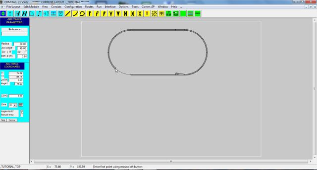
Figure 9-4: closing the layout oval.
In accordance with the segment dimensions used so far, the two unconnected ends of the last added curve segment,
and of the end of the bottom straight track, should exactly match.
This can be checked rapidly by launching the "Check and build module" operation.
Click on the first green icon (starting from left): this is the "Check and build module" icon.

Figure 9-5: "Check and build module" icon
This operation can also be launched from the main menu bar
"Edit/Module" >> "Check and build module"
A window pops up (figure 9-6), and indicates that the connectivity and clearance check has completed with
errors. Errors are flagged with error markers, and one red circle is drawn around the unconnected end of the
turnout, on its deviated branch.
Whenever height clearance errors occur, on segments which intersect with a height less than 7 cm (in HO), they are
flagged with red diamonds (instead of circles).
If the last added curve had not joined the straight segment perfectly, two additional connect (circular) error symbols
would have been drawn on both unconnected ends.

Figure 9-6: after build and check.
Unfortunately, the situation is not always as simple, and on more complex assemblies, accumulated rounding errors may generate an offset of some tenth of millimeter, which is negligible in practice, but sufficient to create a connection error.
A convenient way, to work this problem around, is to use a "circular link" instead of a curve, for closing the loop.
This is the object of next step:
Click on right arrow below.
|