| |
LAYOUT DRAWING: TUTORIAL
Step 10: USING THE CIRCULAR LINK
First of all, delete the last added arc segment (curve):
-
Click on "Delete segment" icon (rightmost blue icon).
-
Click on the arc segment to be deleted (lower left).
-
Click button "Delete" in the confirmation window.
Then click on icon "Add Circular link segment": third yellow icon, starting from left.

Figure 10-1: "Add circular link segment" icon
At this stage, the software waits for two connect points, on free segment ends (figure 10.2).
-
Click a first time on the free arc segment port.
-
Check that, when moving the mouse, the circular segment skeleton connects to the arc segment with the
proper angle. If not, this means that the origin port has not been correctly selected: cancel and resume.
-
Bring the mouse close to the free end of the straight segment, until snapping occurs.
-
Click to confirm placement: the segment is anchored on both ends, but is not fully drawn yet.
The reason, is that the program waits for an optional modification of the circular link radius, in the
corresponding capture field
of the parameter menu.
-
In our example, the radius does not need to be modified. Thus, confirm the final drawing by clicking OK
on bottom of the coordinate menu.
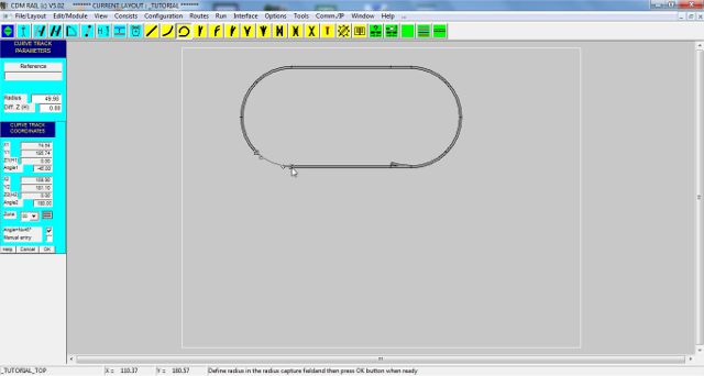
Figure 10-2: skeleton of the circular link, used for closing the layout oval.
IMPORTANT: keep in mind that, quite often, this primitive is the solution for fixing connectivity check errors.
At this point, our oval is OK. But, as happens very often when elaborating a layout, we discover that it would
have been better to add more turnouts, and increase the lengths of the straight sections.
The next section shows how to enlarge the layout, for inserting new items.
And in particular, it will explain how to move a group of segments.
Click on right arrow below.
|