| |
LAYOUT DRAWING: TUTORIAL
Step 5: MOVE A SEGMENT
Click on icon "Move segment" (next figure): this icon is the third blue icon starting from left, in the edit toolbar.

Figure 5-1: "Move segment" icon "
The move sequence consists of three phases:
-
Select segment (or segments) to be moved,
-
Select reference port (end) of segment(s) to be moved,
-
Move segment(s), with reference port as handle, to the targetted location.
Again, have a glimpse at the hints, on bottom line.
For the example at hand, this sequence is the following (see next figure):
-
First, click on the segment to be moved (left mouse button): the selected segment gets highlighted.
-
Then, click on the left-hand end of the segment: a square symbol is skecthed over the selected port, which becomes
the reference port. And the "skeleton" of the segment is superimposed to the highlighted segment.
-
Move the mouse towards the right end of the first segment, until the magnet effect takes place: the "skeleton" of the moved segment snaps to the first placed segment. This is illustrated by next figure.
-
When snapping has occured, just click the mouse left button again to finalize the move operation.
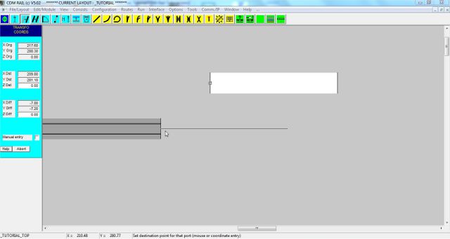
Figure 5-2: Segment selection and move.
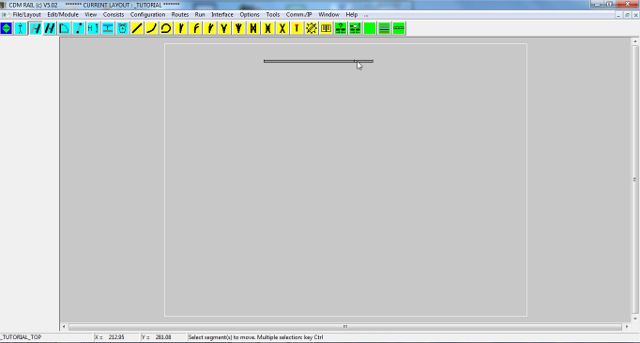
Figure 5-3: After move: the two segments are correctly linked.
Note that, when the moved segment snaps to an existing segment port, the angle of the moved segment automatically
fits the angle of the hosting port.
The move function is also suitable for moving a whole group of segments in one single operation, thanks to the multiple
selection capability: this will be detailed later on, in this tutorial.
The next section deals with adding an arc segment (curve track):
Click on right arrow below
|