| |
LAYOUT DRAWING: TUTORIAL
Step 11: ENLARGE THE LAYOUT /
MOVE A GROUP OF SEGMENTS
In this section, we are going to see how to enlarge a layout for inserting new track segments.
This phase is almost unavoidable when elaborating a layout.
After step 10, the layout looks like this
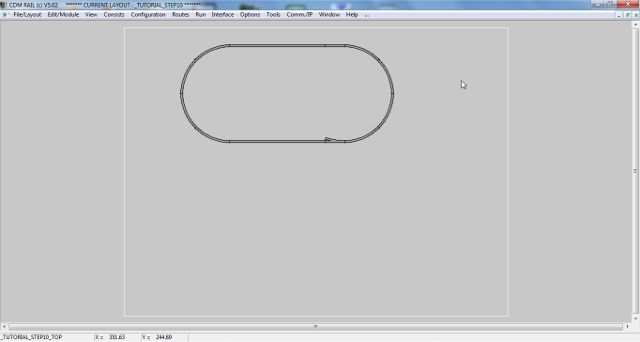
Figure 11-1: current layout state
And we want to expand it to this:
-
lower straight track section lengthened from 100cm to 140 cm,
-
add two turnouts between lower track, and left semi-circle,
-
add one turnout on upper section.
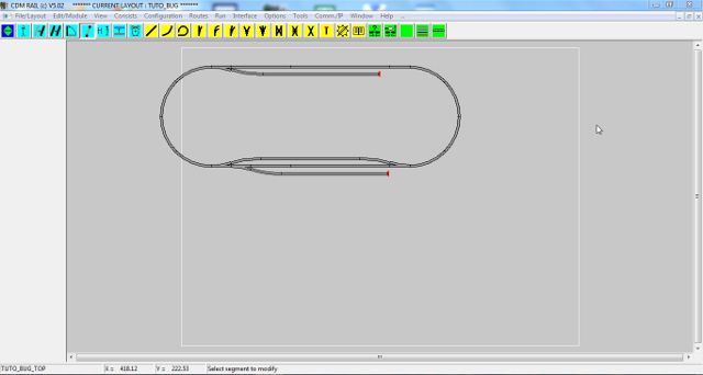
Figure 11-2: the new goal
This operation will be performed according the following substeps:
SELECT AND MOVE LEFT SEMI-CIRCLE
We reuse the "move segment" icon already used in step 5.

Figure 11-3: "move segment" icon
But this time, instead of clicking one single segment, we are going to make a multiple selection over several
segments.
There are two different ways to do this:
-
either define a selection window, with the mouse.
This selects all segments fully included within that selection window.
-
or make a cumulative selection, using the Ctrl key: this will be used later on, in this section.
For the present case, we use the first approach:
-
Move the mouse to the upper left corner of the selection window (outside of any segment), and press
the left button,
-
While maintaining the left button down, drag the mouse to the opposite corner of the selection
(see figure below), and release button.
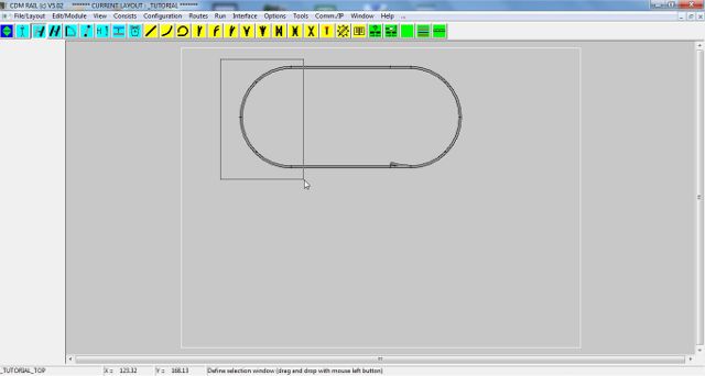
Figure 11-4: defining the selection window
-
On releasing the left mouse button, all segments fully included in the selection window are highlighted.
-
The program waits for clicking on the "handle" (reference) port: see hint on bottom line.
-
After clicking on the "handle" port, the whole selected group is sketched and follows the mouse moves.
Shift the whole selection left, by about 100 cm (see figure below).
-
Click to confirm shift.

Figure 11-5: whole left semi-circle shifted left by 100 cm
ADD EXTRA STRAIGHT TRACK SEGMENT
-
Click on icon "Add straight segment" (as already done in step 1): leftmost yellow icon.
-
Check box "fixed length" in the parameter menu, and set length to 40 cm.
-
Snap segment skeleton to the left-hand port of the already placed straight segment (see figure below).
-
click to confirm.

Figure 11-6: adding an new straight track segment, 40 cm long.
ADD THE TWO LOWER LEFT TURNOUTS
Here, we add the two lower left turnouts, from a track catalog, exactly as done in step 8.
-
Click on icon "Open a track catalog": rigtmost yellow icon.
-
Select library "Fleischmann Profi" as earlier.
-
Select proper type of turnout (right for first instance, and left for second instance).
-
But this time, click radio button 1, as ORIGIN PORT. This selects the end port of undeviated branch
as "handle" port.
-
Snap to lower track path. The figure below is a screenshot immediately before second turnout placement.
-
Click to confirm.
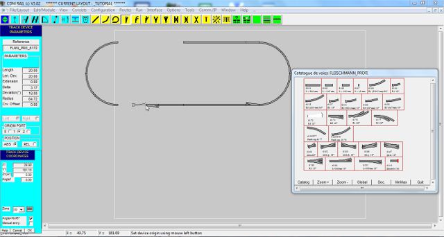
Figure 11-7: Add the two lower left turnouts, from library.
ADD THE UPPER LEFT TURNOUT
Same as above, but snap turnout to the upper arc segment (ORIGIN PORT 0)

Figure 11-8: Add the upper left turnout from track library.
SELECT LEFT SEMI-CIRCLE + TURNOUT GROUP, AND SNAP BACK IN PLACE
Now that we have inserted all what we wanted to insert, we are ready to move back the left semi-circle
(and its new turnout), to the rest of the layout.
This time, we are going to use the cumulative multiple selection method.
It consists of selecting all group items, one after the other, while pressing on the Ctrl key.
In practice, in our case, here is the sequence of operations:
-
Press key Ctrl down (keyboard), and maintain.
-
Click on any of the 4 arc segments of the semi-circle. Any new clicked segment is higlighted.
-
Click on the attached turnout.
-
Release the control key: the program waits for the selection of the "handle" port.
-
Click on the lower right port of the semi-circle for selection.
-
Bring the mouse close to the free left-hand port of the lower path, until snapping occurs (see figure below).
-
Click to confirm move.

Figure 11-9: Snapping the semi-circle group back in position.
NOTE: During the cumulative selection phase, if you click on an already selected segment, this segment
gets unselected.
NOTE: These two ways of performing multiple selections, apply to all transformation operators:
MOVE, COPY, ROTATE, CHANGE LAYER, DELETE
CLOSING THE LOOP WITH A NEW STRAIGHT TRACK SEGMENT
As earlier, we add another straight track segment, to bridge remaining gap, on the upper path.
-
Click on icon "Add straight segment".
-
In the parameter menu, make sure that the "Fixed length" box is NOT checked.
-
Click left mouse button close to the unconnected port of the upper left turnout.
-
Bring the mouse close to the unconnected port, on the left side of the upper path, until snapping occurs
(see figure below).
-
Click to confirm.
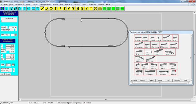
Figure 11-10: Adding a variable length straight segment, to close the oval.
And that's it: here is what it should look like.

Figure 11-11: final result.
In next step, before adding the missing tracks (sidings, ..), we are going to modify the layout bounding box
dimensions, so as to get it larger, and centered on screen.
Click on right arrow below.
|