|
 |
 |
 |
 |
 |
 |
 |
 |
 |
 |
 |
 |
TRACK ELEVATION HANDLING
-INCLINES AND SLOPES-
As explained in note "track colors and layers ", CDM-Rail allows to display different track elevations,
by using different colors for up to 16 different layers.
But beyond display, CDM-Rail also checks for compliance with a clearance of 7cm in HO scale
(and proportional value for other scales), whenever straddling occurs between two tracks.
If this check fails, an error symbol is sketched upon completion of the "Check and Build" operation.
("Edit/Module" >> "Check and build module").
This is the purpose of the tools discussed in this note, for handling track elevation, and building graded inlines.
The recommended approach, for handling track elevations, consists of three steps:
-
Allocate proper layer to any physical level of the layout ,
-
Set (common) elevation of tracks within any physical layer (floor) in the layout ,
-
Generate all graded inclines, linking the different levels (floor) in the layout .
-
At any step, it is possible to globally display the current values of elevations.
TRACK LAYER ALLOCATION
============================
In the following, "plane" stands for "physical level of the layout", with all tracks at the same elevation.
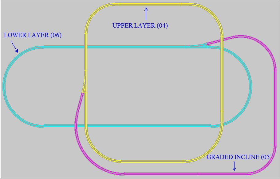
First of all, in order to make the display more readable, it is recommended to set all tracks in a same plane
on the same drawing layer (numbered from 0 to 15), and begin by largest numbers for lowest levels.
And provision should be taken for keeping at least one spare layer number between 2 plane numbers, dedicated to
graded inlines between these two planes: see example below.
Whenever possible, it is even safer to leave 3 or 4 spare layer numbers between two planes: they will be highly welcome
on more complex layouts.
Do not hesitate to modify tracks layers, early in the project.
It is an esay operation in edit modeen ("Edit/Module" >> "Edit module layout (graphics) ").
Click on icon  in the edit toolbar, and select the track segments to be modified.
For this operation, think of using "multiple select": Ctrl key + click on mouse left button.
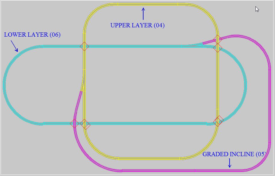
At this point, display if correct, but if the layout (or module) is checked an built
("Edit/Module" >> "Check and build module"), track clearance errors pop up, since all track elevations are still
at their default value: 0. See figure below.
The next step, track elevation setting, is going to solve these issues.
BACK TO TOP OF PAGE
|
|
|
|
|
ASSIGN COMMON ELEVATION TO ALL TRACKS WITHIN A PLANE (PHYSICAL LAYER)
=============================================================================
This operation sets the (common) elevation of all tracks within a layout plane (physical level), in order to comply
with the minimum clearance between two planes (7cm in HO scale).
In the Edit menu ("Edit/Module" >> "Edit module layout (graphics) "), click on icon  .
.
The window below pops up.

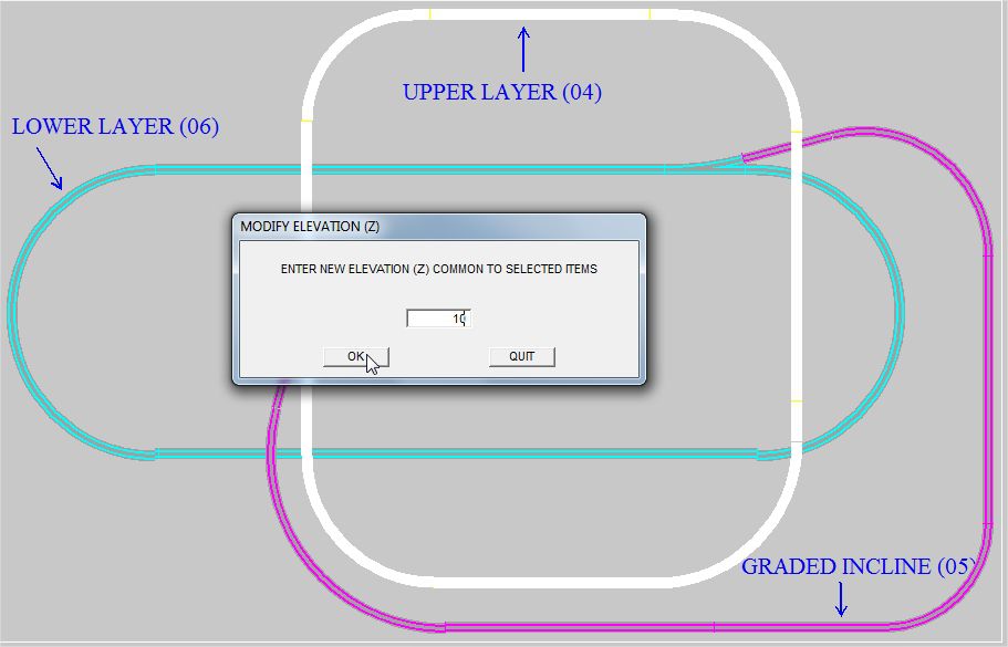
Select mode "Per segment mode ", then click on OK.
Then select all plane segments to be set to the common elevation
The most convenient way is "multiple select" (Ctrl key + click on mouse left button + one last click with Ctrl key
released, for selection enable.
A new window pops up, and allows for setting the new elevation value (in cm) for the selected group.
The next step explains how to define the graded inclines which join the planes defined in this section.
NOTE: For this operation (definition of plane elevation) it is also possible to use the "ramp" mode (see next section),
and specify the same elevation for both start and stop points: faster when there are NOT too many turnouts.
BACK TO TOP OF PAGE
|
|
|
|
INCLINE DEFINITION
====================
In the following "ramp" stands for "incline".
The same operation as before is used ("Edition/Module" >> "Edition du module"), icon , but in the elevation
modification mode menu, the "Ramp mode" is selected instead of "Per segment mode".

A window for incline ends selection pops up :
Click on both ends successively, and define the two elevations in fields H1 et H2.
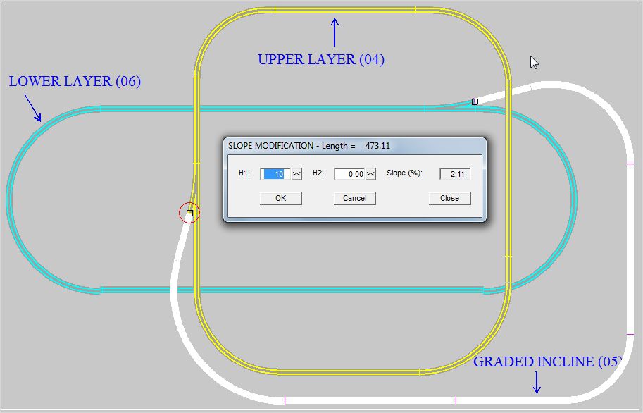
The field on the rigth end of the window displays the grade (in %), corresponding to current capture.
In order to stay "realistic", in the implementation of the physical layout, but also for preventing wheel slippage,
and accelerated wear of rolling stock, it is recommended to stay below 3% grading.
BACK TO TOP OF PAGE
|
|
|
|
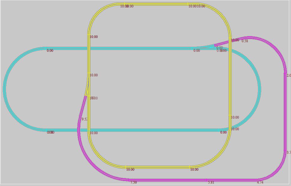
ELEVATION DISPLAY
===================
Upon completion of these operations, and at any step of the process, it is possible to check te current state of layout elevations
by enabling option "SHOW H LABELS" in the Display options menu ("Options" >> "Display").