
 |
 |
 |
 |
 |
 |
 |
 |
 |
 |
 |
 |
 |
POSITIONNING DETECTION AREAS
REMINDER ON DETECTION HANDLING BY CDM-RAIL
DETECTION AREAS ON PLAIN BLOCKS
DETECTION AREAS ON ADJACENT BLOCKS
DETECTION AREAS ON SIDINGS
SPECIAL CASE: "ONE SINGLE DETECTION AREA PAR BLOCK" APPROACH
DETECTION AREA WIRING
REMINDER ON DETECTION HANDLING UNDER CDM-RAIL
In CDM-Rail, the usual namings "stop areas " and "slow down areas" are still used, once in a while,
for consistence with most layout control softwares.
However, in
CDM-Rail, these detection areas are rather intended for synchronizing real trains,
travelling on the real layout, with the corresponding virtual trains, on the PC screen.
The simulation is the real engine for RUN: it sends all turnout commands, and speed commands to any
train, as a function of the virtual train position (on screen).
The whole control strategy relies on that any real train, and the corresponding virtual train, are exactly
at the same location, at any time.
The purpose and function of detection areas is precisely to perform this synchronization between
real train and corresponding virtual train.
-
If the real train is late, compared to the virtual train (on screen), then the virtual train, whenever
it reaches a detection area, is going to wait for a detection notification, which means that the
real train has reached this same area. -
Conversely, if the real train is early, compared to the virtual train, as soon as the detection
notification occurs, the virtual train jumps to the boundary of the corresponding detection area
(on screen).
The detection symbols, which define the detection area boundaries, are USELESS in the simulation
phase. They are useful in mode RUN ONLY, for driving and synchronizing the real layout.
For the detection approach based on current consumption, any detection symbol corresponds to a
physical gap
on one of the two rails (electrical isolation).
NOTES:
Only the "area" type of detection is discussed here (based of current consumption.
CDM-Rail also allows for using location detectors (reed relays, infra-red,...), but this second approach
is less reliable, and thus is not recommended. It will be discussed in another note.
The 3 following sections explain how to place detection symbols, in the case of the most widely used
approach: 2 detection areas par block.
The last section handles the case where one single detection area par block is used.
BACK TO TOP OF PAGE
|
|
|
|
DETECTION AREAS ON PLAIN BLOCKS
Before we start to explain how to place detection symbols, let's remind that these symbols may be
added, modified, suppressed, exactly as signals, through the signal edition menu, from the main
menu toolbar.
"Edit/Module" >> Edit module signals "
The icon group for detection symbols is the second one (see figure below).

Like signals, detection symbols are directional, and may be placed on either side of the track.
The next figure shows the very common case of a plain block, included between two turnout
areas, and bounded by the signals protecting these turnout areas.
In the case of
the "two detection areas per block" strategy, the recommendation is to keep
as close as possible to the common approach, namely one stop area at each end of the block
(even though, once more, CDM-Rail does not operates exactly this way).
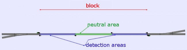
Click for zoom
Each detection area (drawn in blue on above figure) is electrically wired to an output of a
detection module, which sends the detection signal on the feedback bus, whenever a train travels
on it (thus either when entering the block, or when getting close to the end of block).
Conversely, the neutral area in-between (drawn in green on above figure), is not wired to any
detection module.
Please note, in addition, that the turnout areas (in grey, above), are not detected either, and should
not be wired to any detection module.

In summary, there is one detection area at each end of the block.
-
Each of these areas is bounded by two detection symbols, facing each other.
-
One end of each of these areas must coincidate with the "end of block" signal.
The corresponding detection symbol must have the direction opposite to the signal direction:
the signal protects the "outside" of the block (and thus its symbol is directed towards
the "outside" of the block, with our convention), whereas the detection symbol must be
directed towards the detection area, and hence, towards the "inside" of the block. -
The recommended lengths for these areas (X in figure below) are:
-
45-50 cm at HO scale, 60-70 cm for long blocks (> 2 meters),
-
30 cm at N scale, 40-45 cm for long blocks (> 1,2 m).
-
-
The two detection symbols will have the same configuration address, corresponding to the
physical address of the detection circuit monitoring this detection area.
See section 5.2 of manual "RUN mode: getting started".
BACK TO TOP OF PAGE
|
|
|
|
DETECTION AREAS ON ADJACENT BLOCKS
In the preceding section, we have covered the case of a single block located between two turnout
areas.
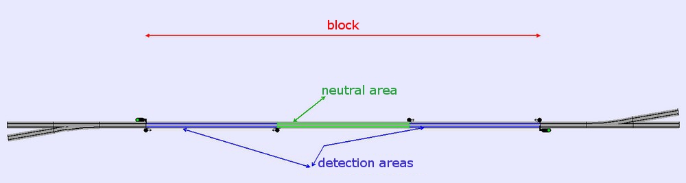
We now discuss the case where the track between two turnout areas is long enough for creating
two blocks, or even more: such blocks are referred to as adjacent.
Adjacent blocks have the specificity of being separated by two signals, at the same place, and in
reverse directions, at their common boundary.
The approach is the same as before: one detection area (drawn in blue in figure below) at each block
end, and one neutral area in-between. The neutral area is optional for short blocks.

But the difference, here, is that there is no need for adding detection symbols at the location of signals,
at the common boundary between the blocks. The implicit detection symbols related to these signals are
used instead, for not overloading the display with two additional symbols.

Of course, it will be necessary to perform the proper configuration operations in order to enable these
implici detectors.
See section 9-3 (Appendix 3) of manual "RUN mode: getting started", for more details on that point.
BACK TO TOP OF PAGE
|
|
|
|
DETECTION AREAS ON SIDINGS
Before getting into the topic of detection symbol positionning on sidings, it is important to review how CDM-Rail
handles
train stop ahead of a buffer stop.
This stop handling can be summarized by two rules:
-
The length of the "buffer stop" item (or segment) is ONLY scenic (ou segment). It is of NO USE for train
travelling. In other words, the effective limit of a siding is the junction between the "buffer stop" item, and
the preceding track item.
As a consequence, it is recommended to reduce this length to about 1 cm, as to minimize the loss of useful
length. -
By default, CDM-Rail orders the train to stop at a fixed distance of this limit.
This fix distance is:- 10 cm for HO
- 6 cm for N

After this preamble, let's comme back to detection symbol positionning on sidings.
The specificity, related to sidings, is that the detection area closest to the buffer stop only needs the "start"
symbol. The junction with the "buffer stop" item implicitly marks the end of the detection area (see figure below).
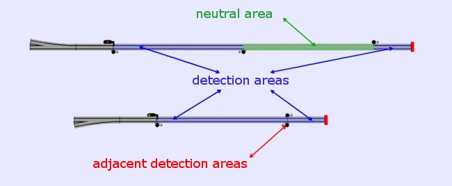
In the case of long sidings, it is possible to use the same rules as for standard blocks.
Conversely, for short sidings, it is mandatory to adapt these rules so as to make sure that, in RUN mode (real
operation), all trains bound to travel on these short sidings, stop close enough to the buffer stop, in order to
free and release the siding turnout.
The best way to meet this requirement, is to reduce the size of the detection area closest to the buffer stop,
down to a length greater than the aforementionned stop distance (hence greater than 10cm for HO, 6 cm for N).
As a matter of fact, CDM-Rail ensures that the real train will proceed until it reaches the detection area, even in the
case of a bad CV4 (inertia) tuning, making the train stop earlier than expected.
This length is, at minimum:
-
12 cm for HO
-
8 cm for N
Of course, this is a minimum. For longer sidings, it is better to lengthen this area, in order to avoid bumping the
buffer stop, if either speed calibration, or CV4 tuning is
not precise enough.
BACK TO TOP OF PAGE
|
|
|
|
SPECIAL CASE: "ONE SINGLE DETECTION AREA PER BLOCK" STRATEGY
CDM-Rail is one of the few softwares able to handle the "one single detection area par block" approach, since it
knows
at any time the exact location of any train, and not only the occupied blocks or detection areas.
The only rule to comply with, in the case where one single detection area is used, is make the ends of the (single)
detection area, match exactly the block boundaries.
The two detection symbols, at the ends of this area, MUST EXACTLY be located at the same places as the block
limiting signals.
The use of implicit detectors, related to signals, also applies in the case of adjacent blocks.
In the case of sidings, however, it is still advisable to keep two detection areas, for the sake of stop precision.
If you still want one single detection area, then it is better not to make it cover the whole siding, but rather limit
its length, as has been seen in the preceding section, for the second area, closest to the buffer stop.
But of course, both
the speed calibration and the CV4 tuning will be even more critical.
REMINDER:
In order to use this approach with maximum safety, you must:
-
enable option "DETECTOR RELEASE CHECKING" (RUN Options),
-
make sure that the last axle of the last car is current consuming enough to trigger detection: this is the only
way to ensure that the real train has left a detection area.
BACK TO TOP OF PAGE
|
|
|
|
DETECTION AREA WIRING
The wiring of detection areas will be discussed in another user note.
In the meantime , see this link.
BACK TO TOP OF PAGE