
 |
 |
 |
 |
 |
 |
 |
 |
 |
 |
 |
 |
 |
Overview of track plan drawing
First contact: CDM-Rail assistant
Creating a layout
Graphic editor
Signaling
Scenery and technical views
Layout modular (or hierarchical) design
================================================================================================
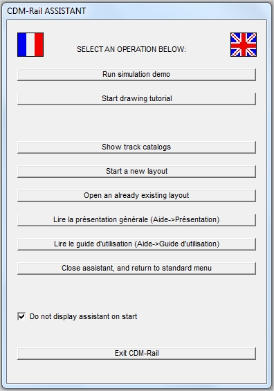
CDM-RAIL ASSISTANT
=======================
On starting the program, an assistant pops-up and allows to rapidly scan the software main functions.
CDM-Rail defaults to french language on first start, but can be easily switched to english by clicking on the british flag, on the upper rigth corner of the assistant.
Language selection can also be done from the main menu bar: Menu "Options" >> "Language".
 |
|
Sorry that the PDF documents for general presentation and user's guide are not translated to english. But this site will soon replace these documents by on-line documentation.
Once familiar with these basic operations, a checkbox allows not to display the assistant at program start, and thus access all these commands (an much more) from the main menu bar.
BACK TO TOP OF PAGE
CREATING A LAYOUT
=====================
Layout creation can be done either from the assistant, or from main menu bar (see following figure).
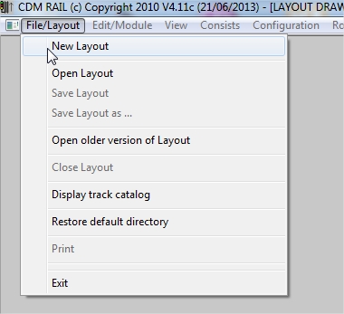
The first step consists of specifying the layout name (if starting from the assistant, this name is automatically allocated), and setting the layout scale.
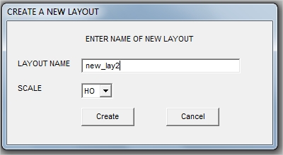
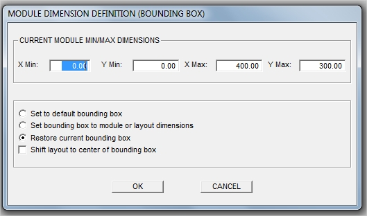
Then, when the targetted layout dimensions are known, it is recommended to specify them as soon as possible:
Menu "Edition/Module" >> "Modify layout dimensions ".
But it is obviously possible to change them afterwards.
BACK TO TOP OF PAGE
THE GRAPHIC EDITOR
=======================
Graphic editor and icon functions presentation.
The graphic editor may be invoked from the main menu bar:
Menu "Edition/Module" >> "Edit module layout".
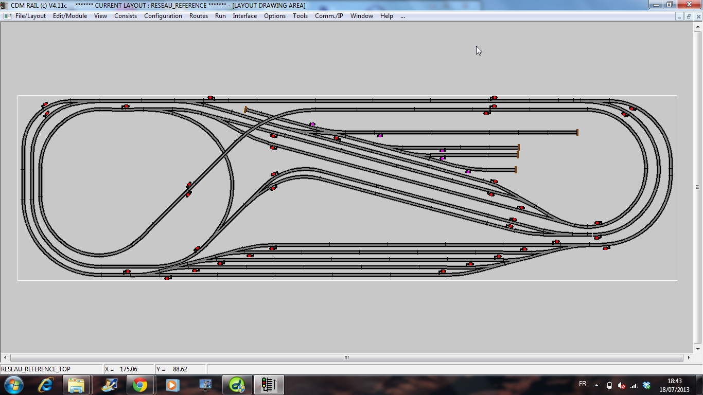
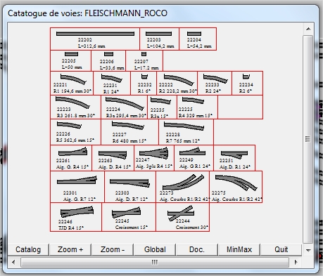
 The layout may be sketched using track librairies, allowing for direct selection of proper manufacter refercnces, with proper track geometries.
When off-the-shelf track cannot be found, it is possible to use the following track primitives
straight track segment |
curved track segment |
||
circular connection |
|||
standard turnout |
curved turnout |
||
symetrical (Y) turnout |
3-way turnout |
||
double crossover |
double slip switch |
||
crossing |
bumper stop |
Any of these primitives can be parametrized in order to allow fitting to any "off-the-shelf" item.
It is also possible to import (menu "Edition/Module") a bitmap file (.BMP), map it as a background for the layout, and use it as a template for drawing tracks from another existing layout, or merely use it as a scenery background.
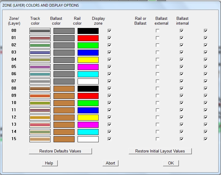
 16 zones (or layers), are available for layout drawing, with customizable colors. Only 2D rendering is currently implemented, but the height of any track item may be tuned so that multi-floor layouts can be readily modeled.
The "zone/layer" options are also accessible from the main menu bar:
Menu "Options" >> "Track colors and options"
 The track measurement tool is especially useful when flexible track is to be used.
 Upon layout capture completion, the connectivity check operation makes sure that all track items are correctly connected, with the right angle, and at right height. The connection errors are displayed as symbols, which may be clicked for additional information.
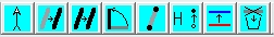 The layout drawing may be modified through the blue icons:
selection, translation, copy, rotation, modification, Z (height) handling, zone (layer) handling, deletion.
BACK TO TOP OF PAGE
SIGNALING
============
The graphic editor also allows for locating signals and detectors (sensors) which will act as a basis for traffic control, in simulation, and in real layout run.
Menu "Edition/Module" >> "Edit module signals"
Several signal types are available, and their orientation is controlled by radio buttons (in the menu on left of screen), or by pressing the space bar.
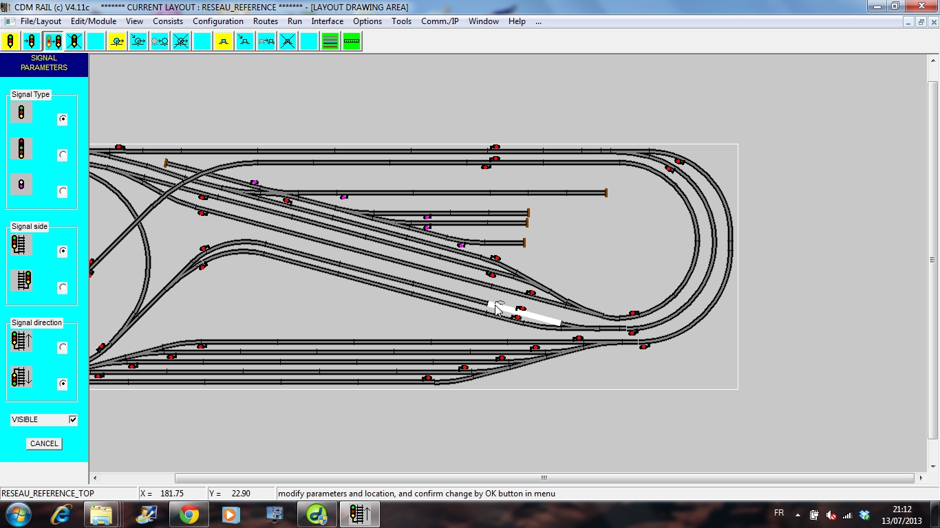
Under CDM-Rail, block partitionning is directly (and implicitely) derived from signal locations.
BACK TO TOP OF PAGE
SCENERY AND TECHNICAL VIEWS
================================
Another editor is available for drawing the scenery, or technical views used for layout documentation.
Scenery edition is invoked by:
Menu "Edition/Module" >> "Module scenery edition".
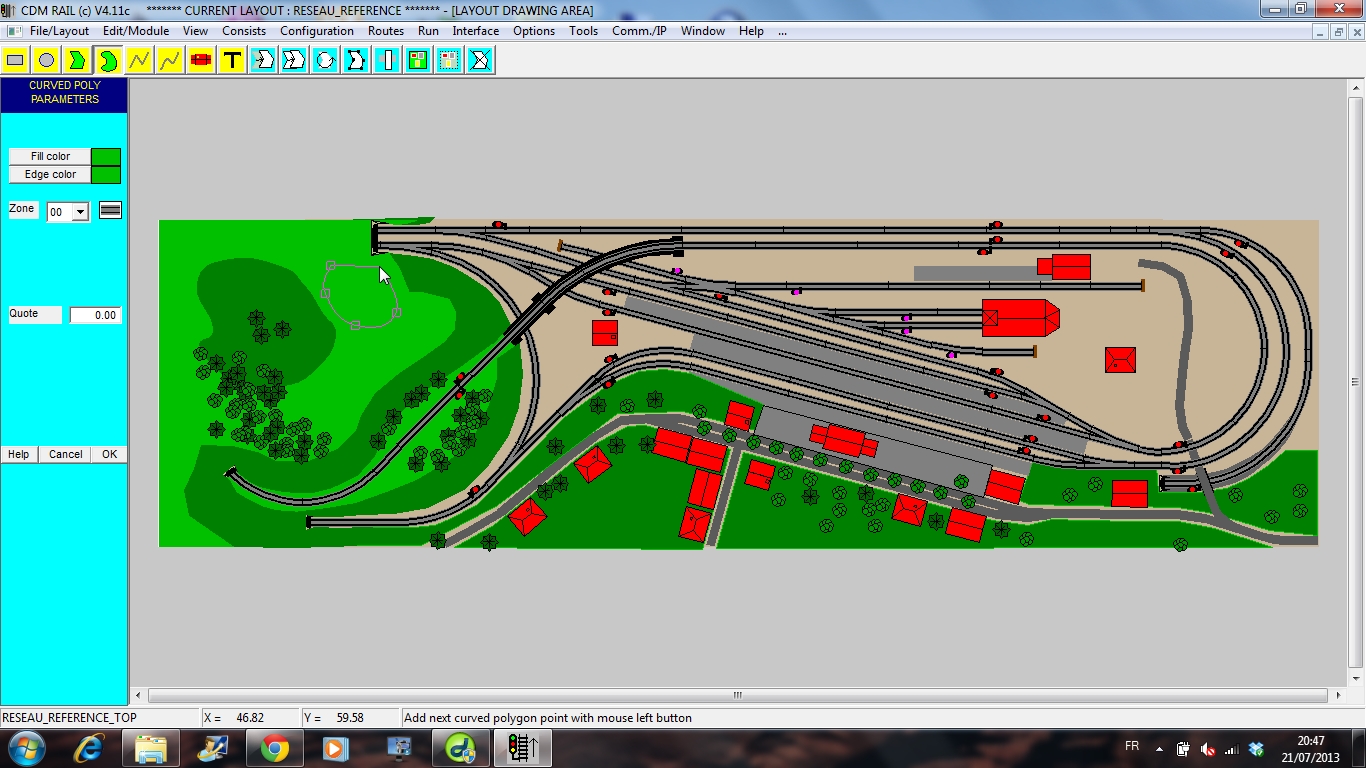
Available graphic primitives:
-
rectangle
-
circle
-
poly line
-
bezier curve
-
polygon
-
bezier polygon
-
texte
Available functions:
-
translation
-
rotation
-
copy
-
modification
-
group (macro)
-
deletion
In simulation and RUN phase, the scenery may be displayed or hidden by pressing keys INS and DEL respectively.
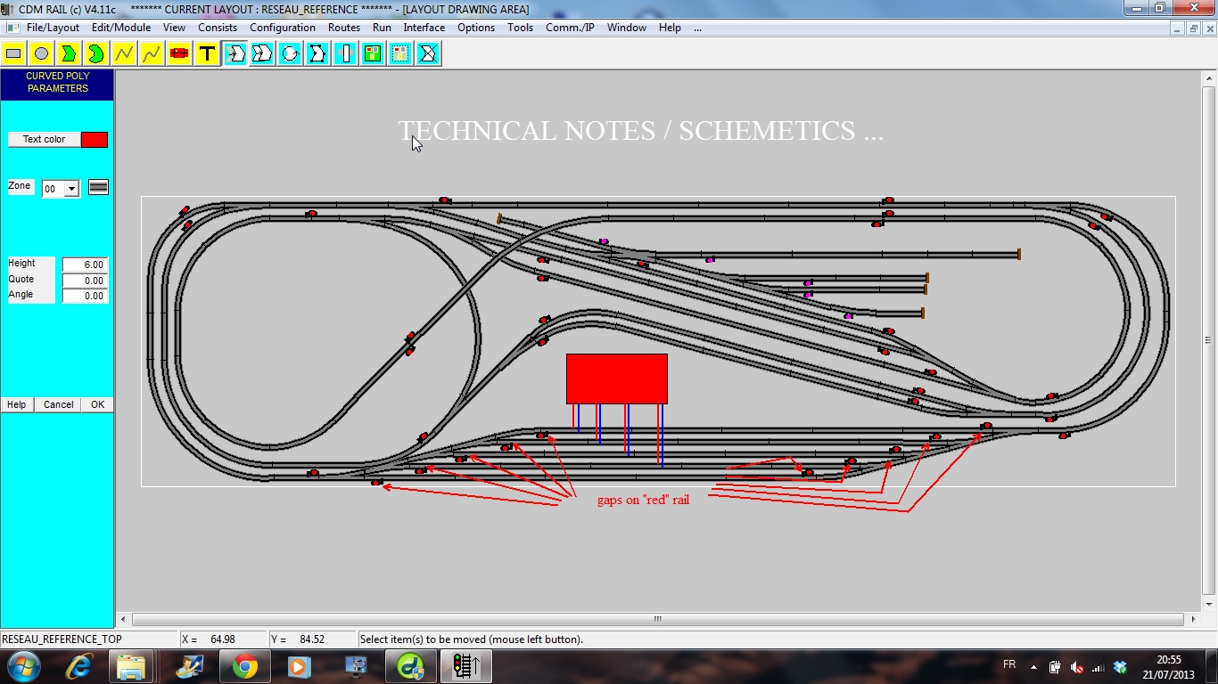
In addition to scenery, it is possible to handle up to 7 independant technical views, which allow for adding technical notes or hints (dimensions, schemetics, ...)
Technical view edition is invoked by:
Menu
"Edition/Module" >> "Edit module annex views ".
BACK TO TOP OF PAGE
MODULAR (OR HIERARCHICAL DESIGN)
======================================
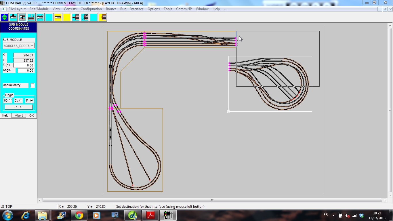
The graphic editor allows for building a layout as an assembly of modules, as for a real layout. Any module may be drawn independently of its neighbours. This hierarcical mode is especially useful for modelling club or association modular layouts.
BACK TO TOP OF PAGE