
 |
 |
 |
 |
 |
 |
 |
 |
 |
 |
 |
 |
 |
Stepping towards "RUN" (software driven layout)
"RUN" mode: what is it?
Step # 1: connecting to the command station
Step # 2: first basic operations
Step # 3: turnout configuration
Step #4: detector configuration
Step # 5: "Simplified RUN" (or "control panel") mode
Step #6: train configuration and speed calibration
Step #7: full "RUN" mode / CDM-Rail driven layout
-
Starting RUN: initial train placing
-
Stops and restarts upon disturbances
-
Stopping and restarting RUN sessions
AND FINALLY, FOR MORE DETAILS...
================================================================================================
"RUN" MODE: WHAT IS IT?
=========================
This section deals with the wide topic of computer driven layout.
But before getting to that point, it's important to emphasize that there are three different levels of
digital
layout handling:
-
The FIRST LEVEL is the one available in starting sets:
one command station,
one or more manual throttle controllers,
and trains are controlled "at sight", without any block security.
The corresponding wiring is very straightforward and simple, and the overall implementation is cheap.
At this level, what CDM-Rail can offer, is the creation of additional software throttle controllers,
as well as a CV programming interface.
Only steps 1 (connecting to the command station), and 2 (first basic operations) are relevant.
-
The SECOND LEVEL provides, in addition, the ability to control turnouts from the PC screen.
However, in order to do that, it is necessary to add accessory decoders, controlled from the command
station, in order to electrically switch the turnouts.
At this level, if the layout has been drawn using CDM-Rail, the software is able to control the turnout
states by mouse clicking on turnout symbols.
See steps 3 (turnout configuration) et 5 ("SIMPLIFIED RUN" mode ).
-
The THIRD (and last) LEVEL ( "RUN" mode ) aims at providing the whole layout block security from
the software. This phase is more constraining, and costly, since it requires that detection areas be
installed on any block.
These detection areas are wired to feedback modules, which may significantly increase the overall cost,
for average or large layouts.
And the wiring, which was very simple in first approach, is getting much more complex.
For this last phase, see step 4 (detector configuration), 6 (train speed calibration),
and 7 (full RUN mode: layout driving by CDM-Rail).
In summary, the full RUN mode involves quite a lot of preliminary (and prerequired) operations:
-
Intensive simulation, checking for fluent traffic, and efficient block partitionning.
-
Careful selection of the whole digital system (command station, turnout decoders, feedback modules).
-
Choice of the detection strategy, with one single detection area per block, or two.
CDM-Rail is one of the (very) few softwares able to handle security with one single detection area per
block. -
A careful layout wiring, which is the ultimate key for safe operation.
BACK TO TOP OF PAGE
|
|
|
|
|
STEP # 1: CONNECTING TO THE COMMAND STATION
================================================
The following command stations are currently supported by CDM-Rail:
-
All Lenz command stations (Xpressnet protocol),
-
Uhlenbrock Intellibox I (P50X protocol),
-
Fleischmann Twin Center (P50X protocol),
-
Roco Multimaus (and its amplifier), together with Paco's GenLIS88, or XIS88 (Xpressnet protocol),
-
SPROG3, together with LDT HSI88 / HSI88-USB for feedback (specific protocols),
-
ESU ECOS (specific protocol).
A command station (or "server") can be accessed from the main menu bar.
(Thumb "Interface" >> "Start a server")
A list of available servers then pops up in a new window

Select server in the folding list, and click OK.
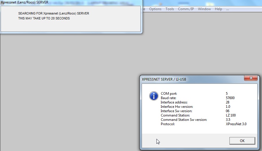
Depending on the selected server, the connection may take effect at this point, or an extra option window
may show up.
In the case of a "COM" port, or "USB" port link , the COM port is automatically searched for.
If the connection fails, an explicit error message notifies it.
If it succeeds, a window pops up, and lists the COM port number, the serial link baud rate, and the server
version number.
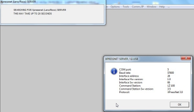
Click to zoom
BACK TO TOP OF PAGE
|
|
|
|
STEP # 2: FIRST BASIC OPERATIONS
=================================
The following operations are possible (from CDM-Rail) immediately after connection to the command station:
-
Create one or more throttle controllers,
-
CV programming,
-
Stop and restart the command station.
CREATING A TRAIN THROTTLE CONTROLLER
(Thumb "Interface" >> "Create a new throttle ")
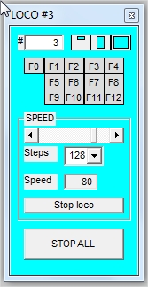
The controller is displayed with an initial address at 0 (field #).
The address of the loco to be controlled should be written in that same field.
Once this is done, the speed and functions 0 to 12 of the specified loco can be controlled.
The controller size may be reduced down to about
1/3 of default height, by clicking on the leftmost icon,
in the group of three icons next to the address field.
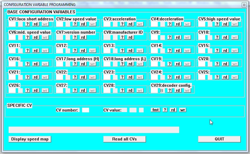
CV PROGRAMMING
(Thumb "Interface" >> "CV Programming")

Click to zoom
BACK TO TOP OF PAGE
|
|
|
|
|
STEP #3 : TURNOUT CONFIGURATION
===================================
The CONFIGURATION operations are intended for assigning consistent addresses:
-
on the one hand on the digital hardware (on-board decoders for locos, accessory decoders for turnouts,
signals and actuators, and feedback modules), -
and, on the other hand, on the software in order to allow it to send commands to the proper decoders,
or retrieve detection information from the proper feedback modules.
These operations are useful only if connected to a command station. They are totally useless in simulation mode.
Whatever the configuration type, all these operations go through thumb "Configuration" in the main menu bar.
-
Train configuration
-
Turnout configuration
-
...
The common toolbar for all these configuration operations consists of 5 groups of 4 icons, one for any
configuration type ( locos, turnouts, signals, detectors, actuators).
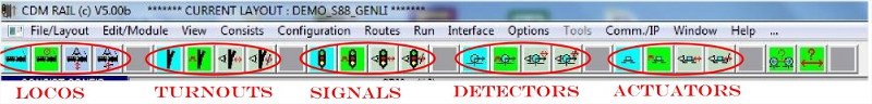
In any group,
-
the first (blue) icon is intended for setting the configuration parameters (address, ...),
-
the second (green) icon is intended for testing proper operation of the item under configuration,
-
the two grey icons allow to display configured items, and unconfigured items, respectively.
In this first approach, only turnout, detector, and loco configurations will be discussed.
However, signal and actuator configurations are also operational, and compatible with off-the-shelf decoders.
TURNOUT CONFIGURATION
The way to enter turnout configuration is to click on the first (blue) icon of the second group of icons, then
select the turnout to be configured (mouse click), and assign its address.

The test mode (green icon in the group), enabled after connection to a command station, displays a similar window,
with "radio" buttons which allow to test all turnout states.
BACK TO TOP OF PAGE
|
|
|
|
|
STEP #4: DETECTOR CONFIGURATION
===================================
The detector configuration is similar to the turnout configuration, but in general takes place much later in
the layout building process, since the wiring of feedback (detection) modules is a long task.
CDM-Rail handles two types of feedback:
-
"RS/Lenz" feedback,
-
"S88/S88N" feedback.
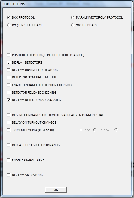
The feedback type must be specified in the RUN options menu
(Thumb "Options" >> "RUN")
Then, the detector configuration menu should be invoked
(Thumb "Configuration" >> "Detector configuration ")
And in the configuration toolbar which appears , ...
... click on first (blue) icon in the 4th icon group.
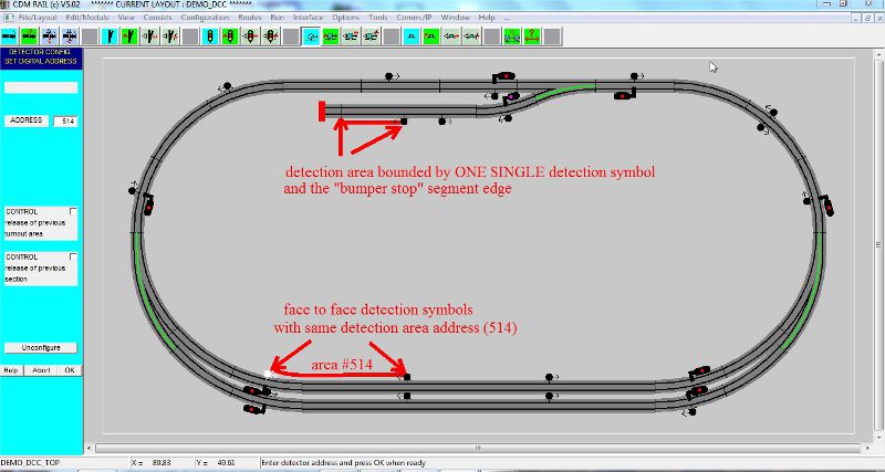
From that point on, it is possible to assign (one at a time) the addresses of detection symbols, previously
located with the same editor as for signals. Whenever an address is allocated to a detection symbol, the address
of the facing detector (on the other side of the detection area), is automatically set to the same value, since
this is the address of the detection area in-between.
The following figure illustrates the case of a "RS_Lenz" feedback, which starts from address 513 (according to
Lenz convention).
In the case of a "S88/S88N" feedback, the address range starts from 1.
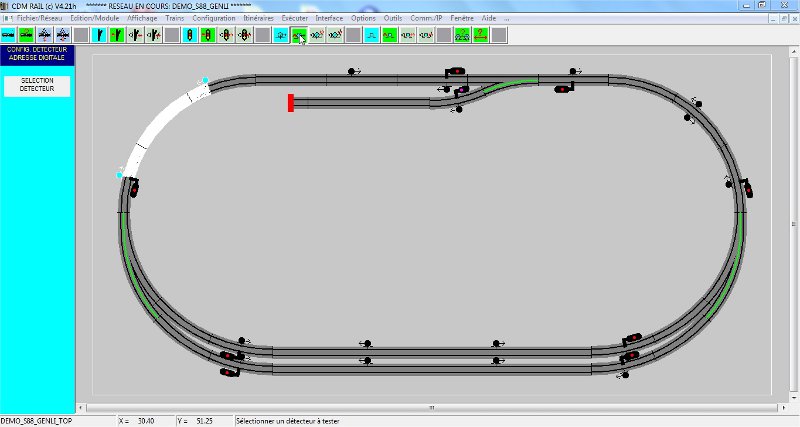
The test mode (green icon in the group), is accessible after connecting to a command station, and displays a
similar window.
In this mode , if a loco travels on the layout, the detection areas are highlighted whenever the loco straddles
over them. This provides a friendly tool for checking that real feedback (detection) addresses, on the real layout,
match the
addresses allocated during configuration, in CDM-Rail.
BACK TO TOP OF PAGE
|
|
|
|
|
STEP # 5: "SIMPLIFIED RUN" (or "PANEL CONTROL RUN" ) MODE
===========================================================
The "simplified RUN" mode is not a real "panel control" mode since block security is NOT implemented in
that specific mode.
It allows:
-
to control turnouts states by simple mouse click,
-
to visualize the detection area occupancy states, according to train locations.
Make sure that display of detection symbols, and detection areas is enabled, in the RUN option menu:
(thumb "Options" >> "Run" )
In order to start the "simplified RUN" mode, go through the following steps:
-
connect to a command station : thumb "Interface" >> "Start a server",
-
start "RUN", with NO trains placed on screen: thumb "Run" >> "Enter run mode",
-
The trains may be controlled either with a hardware throttle controller, or with software controllers
created in CDM-Rail before starting the RUN.
The on screen behaviour is quite similar to what can be observed in the detector configuration mode (see
previous section): namely, detected areas are highlighted in white, to indicate occupancy by a loco, or by a car with
resistive axle.
The difference lies in the ability to control turnout states with the mouse, and also in that the RUN menu
(see next figure) pops up, for a more fricndly control of the layout.
BACK TO TOP OF PAGE
|
|
|
|
|
SPEED # 6: TRAIN CONFIGURATION AND SPEED CALIBRATION
=========================================================
In order to configure a train address, select the following in the main toolbar:
(Thumb "Configuration" >> "Train configuration ")
And in the configuration toolbar, ...
... click on the first (blue) icon in the first icon group...
... select the train to be configured in the train gallery window which appears...
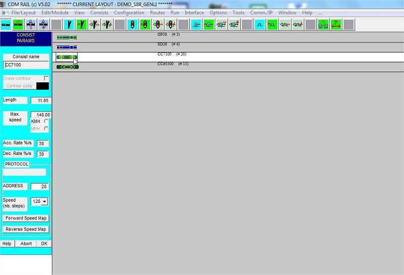
... set address train, and click OK.
At this point, everything is almost OK. The only missing operation is matching the real speed of the real loco
(on physical layout) with the speed of the virtual loco on screen (which is the exact scaled speed of the train).
This tuning can be achieved through modification of the speed CVs in the loco decoder (CV5, CV6, et CV2).
However, CDM-Rail offers another solution, which avoids modifying these CVs.
This solution consists of using the forward and backward speed tables, which allow to memorize the DCC
speed steps to be sent to the command station, ranging from 0 to 126, as a function of loco speed.
The automatic calibration procedure assumes that two looped routes (named CALIB_POS et CALIB_NEG)
have been previously created. During calibration, these two routes should be traveled at constant maximum
speed, by the train under calibration.
This procedure is initiated by clicking on the green test icon, in the "train configuration" group, once the real
loco or train to be calibrated
has been placed on route CALIB_POS.
Upon completion of this calibration procedure, the calibrated train is ready for full "RUN"..
The detail of this procedure is described in document "Run mode: getting started".
BACK TO TOP OF PAGE
|
|
|
|
|
STEP #7: FULL "RUN"
=======================
The first (and single) thing to do, once connected to a command station, before starting RUN, is to place
trains on screen, attached to routes or not, at locations corresponding to their real equivalent locations, on
the real layout.
Also make sure that any train is in its correct direction: a train starting in opposite direction with respect to
what it should, will jeopardize the overall layout operation.
Train positionning occurs exactly as for simulation.
Thumb "Consists" >> "Place"
Then:
-
select any train to be placed, from the train gallery or in the train list in the place menu
(List "Select Consist"), -
assign it to a specific route (list "Route seclection"),
-
and click it on the proper layout section (see figure below).
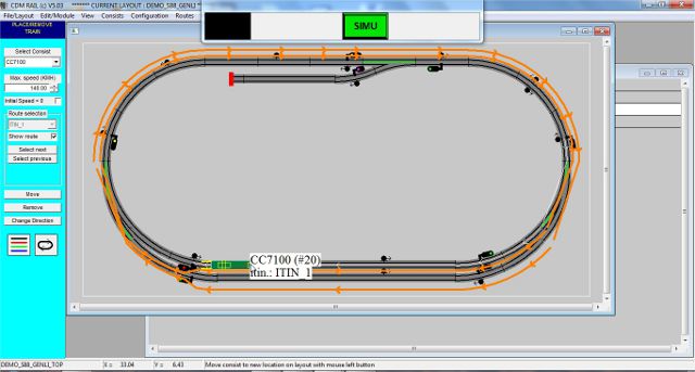
Click to zoom

Since, quite often, the simulation has been previously carried out (for checking proper operation and chasing
bottlenecks), if an initial placement simulation context
has been saved, the most efficient and simple way of
setting initial trains location, is to restore such a simulation context.
Thumb "Consists" >> "Restore a Simu/Run context"
Whichever placement mode you use, the (floating) RUN menu appears, and the RUN mode may be readily
launched by pressing button "RUN".

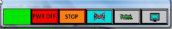
After pressing button "RUN", the menu is now populated with 6 buttons.
Here we are! It runs.... At least until it runs ... into problems (see below).
But on a layout which has been carefully wired, and previously simulated, running locos with good current
collection, it is quite common to run for several hours with no need to stop the software.
BACK TO TOP OF PAGE
|
|
|
|
|
STOPS AND RESTARTS UPON DISTURBANCES
There still remain the unexpected events which are "the beauty" of real layout operation:
-
derailments,
-
unexpected wagon decoupling,
-
getting stuck on a bad current collection.
Stops induced by bad collection do not generate major issues:
the real train does not reach next detection, and hence, its virtual (simulated) equivalent stays waiting ahead of
the next detector ... which disables the corresponding block, and gradually stops all following trains, block after
block.
In general, a light finger impulse on the reluctant train will make it get out of the bad current collection area,
and everything will restart gradually, as soon as blocks get released, with no need for a more severe intervention.
Derailments and uncouplings, in general, force the RUN to be stopped, either manually from the menu,
or automatically, in the case where a short-circuit occurs, which generates a "power-off" on the tracks.
If there is no short-circuit, the simplest action is to click on button "STOP", in the RUN menu: this is the
EMERGENCY STOP .
In that case, all trains stop immediately, and the problem can be solved. You then need only to click on the same
button (renamed as "GO"), in order to restarts the whole layout.
The leftmost box is not a button: this is the status indicator.
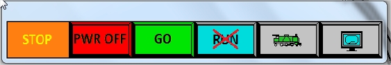
NOTE: pressing key "SPACE", on the keyboard, has exactly the same effect, as pressing button STOP/GO
in the RUN menu.
In case of short-circuit, or if button "PWR OFF" is pressed, in the RUN menu, the behaviour is different.
All trains stop immediately, but their cruise speeds are all reset to 0.
As a consequence, when button "GO" is pressed for restart, the trains don't restart.
This is a security, as to be able to restart trains selectively, if required.
At this point, there are two options:
-
Either restart trains individually, by setting the cruise speed cursor back to nominal speed, on any throttle
controller dedicated to any train. All these cursors have been reset to 0 on power off.
Reminder: in the case where one single throttle is displayed at a time, you step from one throttle to the next
one by using key TAB, on the keyboard. -
Or restart all trains simutaneously. This operation is accessible from the "RUN" menu, as follows:
-
click on 5th icon of the first row (with a loco icon), as to display the "train operations" row of buttons.
-
In the second row, the button which controls general restart of all trains, is the 3rd one (loco with
arrow ahead).
-
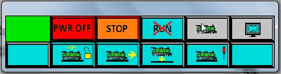
The 4 active icons of this second row are:
-
button #2:
immediate stop of all trains, with cruise speeds reset to 0 (loco with "0" and open padlock).
The open padlock means that all resource locks and reservations are released for all trains. -
button #3:
restart all trains (loco + arrow ahead). -
button #4:
on-the-fly positionning of a new train (loco + arrow down). -
button #5:
gradual (clean) stop of all trains on next block (loco + red signal).
BACK TO TOP OF PAGE
|
|
|
|
|
STOPPING AND RESTARTING A RUN SESSION
Whenever you click on the "End of RUN" button (RUN with a red "X"), any train stops at its current location,
and a specific simulation context, named "_RUN_CTXT", is automatically generated.
The "gradual stop" button (button #5 mentionned above, in the "train operations" row), allows to make trains
stop "cleanly", at ends of blocks, as to be in "clean" initial locations in case of restart.
This context may be restored in a later session, for resetting virtuals trains, on screen, on locations where the real
trains have been left, on the real layout.
Thumb "Consists" >> "Restore a Simu/Run context"
Then in the context selection window, select context "_RUN_CTXT": all virtual train locations now match the real
trains, if they have not been moved in the mean time.
The "RUN" menu pops up, and clicking button "RUN" will restart everything.
NOTE: If all trains have been stopped before ending the run, they must be restarted, either train after train
(acting upon the throttle cursor), or globally (button #3 in the "train operations" row).
After an end of RUN, if trains are still in position on screen, no need for restoring context _RUN_CTXT: just click
on button "RUN".
BACK TO TOP OF PAGE
|
|
|
|
|
|
FOR MORE DETAILS ...
... see manual "RUN MODE: GETTING STARTED"
BACK TO TOP OF PAGE